Photo 1 This little 8bhp @ 850rpm engine was a sad sight sitting on a pallet, after being rescued from an event at Walhalla some years ago. After awaiting restoration for quite some time, that day finally arrived. We poured distillate into the valve chest and cylinder, and sprayed the rest of the engine - indeed a good wetting. A week later, when the distillate had soaked through, we were able to start the strip down.

Photo 2 The indefatigable junior apprentice, ‘Wee Duncan’, attacked the inspection cover to the crank case with a ½” Whitworth spanner, and very soon all was revealed; a crankcase full of goop with rusty droplets on all the bright bits. The engine was seized, but redeemable with not too much effort.

Photo 3 The Master and the Apprentice start to strip the engine to component parts. We thought at first, that the big end was loose (knocking) but it turned out to be the ‘flogged’ flywheel key…clunk, clunk, phew!...that’s easy fixed.
Within a few days, ‘we’ had the engine stripped, cleaned, and un-seized, and then back together. The lad learned a few new things, such as how to thoroughly clean an engine, make new gaskets, new tinwork for the cylinder lagging, and remove old slot/dome-head screws! And then, he went to the store and came back with some nice new, (not) zinc-plated screws!
“No, No, laddie, we will use the old ones”, I said.
“But Pappy, they are all bent and rusty!”, Wee Duncan replied.
“Pass me the 12oz ball pein hammer”, I said while tap, tap, tapping away. “See laddie, like new!”
While twice heating them to red heat to unseize them, we had, of course, also annealed them ready to pein into shape.

Photo 4 The engine is re-assembled and ready to test on air. Wee Duncan selected a new/old flanged globe valve to fit his ‘does all’ test - a ¼” Jamec air hose nipple!
During the strip and clean, we removed all the dry packings, polished the piston and valve rods, checked the piston valve and rings, lubed everything, and tested it accordingly as above.
This little engine was made in 1940 to War trim - all the bright work was undercoated in red oxide and painted silver, with the rest of the engine in grey undercoat and green. There was no polished metal, but a lot of extra shop time went into obviating the need to polish, or at least into keeping the metal clean. There it was under the paint…polished, machined iron!

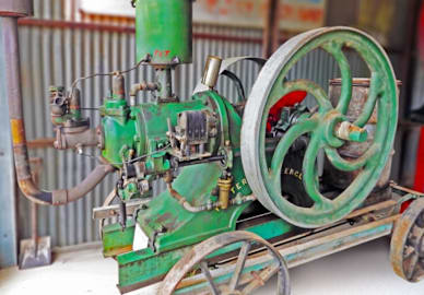
Photo 5 The engine is a piston valve type with an auxiliary piston valve governor, worked by flyballs and springs through bell cranks and rods. It is designed, of course, to be a generator engine with 8bhp @ 850rpm and is fitted with a 5 ‘A’ belt flywheel - no shortage of drive there!
We happened to have a 32 - 40 volt DC generator which was very affected by having been exposed to damp air in a shearing shed but, after only a few days work on the armature, all fields covering the brushes and their mechanisms tested OK.
“Now we will test it, laddie”, I said.
“But Pappy, we have not fitted the engine yet!” Wee Duncan reminded me.
“No laddie, we will use a battery but watch this clip on the test leads and whirr…it’s motoring! You see, Wee Duncan, it is a direct current generator. If it will motor, it will generate! Now, let’s get painting and find some matching ‘A’ section V-belts”.
Coincidently, the GMF generator was also made in Melbourne in 1949.

Photo 6 The setup is on base frame 6, with 50 volt globes @ 40 volts, and ‘incandescent’. We were able to run the engine @ 650rpm, which is 200rpm slower than the book revs. Duncan is firing the boiler intermittently, as he wants to check the engine; all 100%. We made a nice switchboard, but we don’t have any electric meters, i.e., 3” to 4” diameter, voltmeter 0-60 volts, and ditto amps.

If anybody can help with sourcing these, please call Andrew (and Duncan) on (03) 5797 0241. *Andrew Forbes